Underwater Laser Scanning for Subsea Pipeline Inspection
Underwater Laser based micro-bathymetry is becoming a new standard for subsea pipeline and asset inspection. As the industry moves to deeper and more hostile environments for extraction of oil, technology to manage the risks involved in these environments are critical. This became most evident during the Deepwater Horizon sinking in 2010 and the subsequent free flowing well. The economic and environmental cost incurred whenever such events occur is a constant reminder of this need for responsible and safe continued operations. A key aspect to this safe continued operation is inspection monitoring maintenance and repair (IMMR) activities. Major oil producers recognize this requirement and have begun to employ underwater laser scanning technology for a variety of applications.
C & C Technologies is setting new standards for subsea asset inspection through the use of underwater laser scanning technology provided by2G Robotics. Laser scanning has a number of benefits for close range inspection over traditional acoustic techniques, providing 100x the resolution. This increased resolution lets operators see and measure details that were previously unavailable. By reducing uncertainty about the condition of an asset, improved decision making is possible, thus reducing risk and ensuring continued safe operation..
Critical Pipeline Features
Pipelines that are laid on the seabed are exposed to a number of external hazards. Anchor drag damage, seismic activity, currents from the sea itself through to corrosion, pipeline movement and erosion resulting in free-spans.
Anchor Drag Damage
Anchor drags can result in scoring and bending of the pipelines. Assessing the optimal corrective action in these situations is highly valuable. By capturing a precise 3D model, engineers can evaluate if the pipeline can be acceptable without significant repair. When repair is a viable option, highly detailed data enables restorative planning with confidence.
Free Spans
Sediment transport due to seabed currents can result in unsupported pipeline spans (free-spans). As these spans grow, the stress on the pipe increases as it holds up more and more of its own weight. If these are not addressed they can lead to failures and ultimately ruptures.
Both of these issues are critical to the longevity of pipeline assets and without highly precise information, it is possible to miss potentially critical information.
Challenges With Existing Technology
Existing subsea metrology techniques have been unable to provide the level of detail afforded by underwater laser scanner technology. Video on its own provides an easy to understand and interpret qualitative assessment of an asset. From imagery, damage locations can be observed but assumptions about the sizes of features observed are required when making decisions and this can lead to incorrect assumption resulting in unnecessary expenses or asset failures. The use of laser scaling techniques can aid in size estimations but true measurements are not achieved.
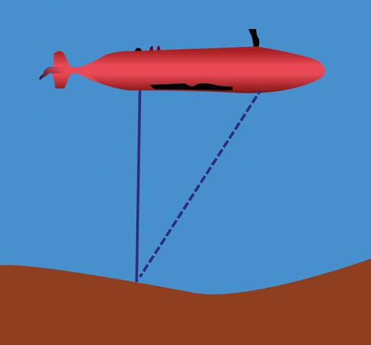
Multibeam sonar is the traditional technique for collecting measurement data over pipelines. This technique is very good at collecting data over long ranges, particularly in high silt conditions where optical technique will fail. However, since sonar is a mechanical wave, as it propagates through the water, the wave front spreads apart like a ripple on the top of the water and thus the area over which the sonar signal takes its measurement is relatively large. Due to this large acoustic footprint, sonar systems are not able to resolve fine features and may incorrectly report there to be returns at the edge of a target where no target exists, resulting in potentially misleading information.
Laser scanning, while not able to penetrate through silt and travel larger distances, is able to resolve very fine details and accurately define the edges of structures. The graphic below demonstrates with a simple example the differences in the physics between sonar and laser prorogation.
View animations describing this behavior here: www.2grobotics.com/MTR201405
Laser Scanner Integration and Deployment
2G Robotics underwater laser scanners operate using a trigonometric approach. There are two key components, the laser emitter and the receiver. By projecting a 50 degree fan of laser light from the emitter, a stripe of laser light projects on the target surface. The light from the target surface scatters in all directions with a component of this light reflecting back to the optical sensor (the receiver). The optical sensor measures the angle to the laser light all along the line, based on knowing this angle as well as the relative positioning between the laser emitter and receiver, a profile of points is calculated. Moving the laser plane, either with an integrated rotary actuator or an external system, a series of adjacent profiles is collected to build a complete 3D point cloud representation of the surface of the object being scanned.
For profiling pipelines, the laser scanner integrates with vehicles in a near equivalent manner as multi beam sonar. When using an external system to move the laser for capturing adjacent profiles such as pipeline profiling, precise positioning is required. To synchronize the laser data with the position information, the data is time tagged and synchronization between the clocks is accomplished with standard PPS (Pulse Per Second) protocols. Additionally, an accurate understanding of the alignment between the positioning system origin and the sensor origin is required, and this is achieved through standard patch tests.
When integrating with an AUV, the laser and the sensor components can independently be mounted into the vehicle in a configuration that preserves the hydrodynamics of the AUV. A calibration process is then performed by the operators to determine the accurate relative positioning. Communication with the 2G Robotics system is accomplished through a binary protocol and code libraries can be provided.
When integrating with an ROV, the laser and sensor housings can remain on the spacer arm and installed directly onto the vehicle with no additional sensor calibration required. It is also possible to mount multiple synchronized systems to an ROV for scanning the sides of pipelines. The systems are controlled through a standard 10/100 Ethernet link to the surface and data is published in standard LAS format for use with standard survey packages.
C & C Technologies Results
C & C Technologies is a leader for subsea pipeline inspection pioneering the use of AUVs for deep water surveys. It has performed more than 325,000 km of inspection and currently have a fleet of four Hugin AUVs. Through adding enhanced sensor packages to its Hugin VI vehicle it has created an inspection class AUV for high detailed pipeline surveys, where these surveys have traditionally been performed using ROVs. In its inspection class AUV, C & C Technologies has incorporated a number of sensors including:
- MicroTesla magnatometer
- High Resolution Digital Still Camera
1360 x 1024 pixels
~ 6 x 4.5 m coverage from 8 m altitude
~ 5 mm resolution
- Multibeam Sonar
Kongsberg EM 2040
200/300/400 kHz
140° Swath
400 beams – .7° x .7°
Water Column Support
- Micro-Bathymetry Subsea Laser Scanner
2G Robotics ULS-500 Underwater Laser Scanner
50 degree swath
1400 beams
~1mm range resolution
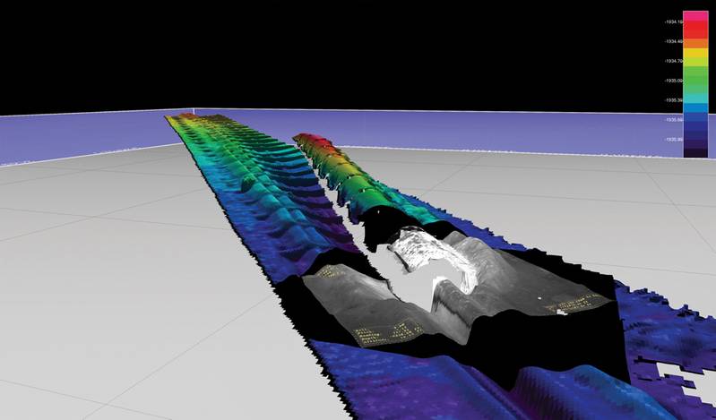
In the Fall of 2013, C & C Technologies took delivery of the ULS-500 systems and performed a number of inspection demonstrations with some of their customers. Using its unique suite of sensors, the company was able to determine information that previously would not have been feasible from an AUV. In one particular instance, an anomaly was identified using the magnetometer. Nothing of note was identified through the sonar data. The high resolution camera was able to very clearly determine that a section of pipe abutted the pipeline being inspected. Using the laser scanner, the geometry of the pipe was understood as was the relative position between the pipe and the surroundings. Based on the profile data and fitting circles to this data, it can be clearly seen that the main 8-in. pipeline is not in a free-span state, while the smaller adjunct pipeline is suspended over the ground at this location. Unlike sonar that will provide false returns at the intersection between the ground and the pipeline, the laser data is crisp and does not contain any false returns, allowing for this sort of small offset free span assessment to be performed using only data from the top of the pipeline.
At other locations during these initial inspections, a sleeper and buoyancy collars were inspected, the resulting laser data is shown below.
By having both the laser data in addition to the still imagery, C & C Technologies is able to generate 3D pictures by laying the pictures over the laser scanner based micro-bathymetry.
Since the trails last year, C & C Technologies has continued to operate their inspection class system. With underwater laser scanning now the standard for sub-sea pipeline inspections, they have just completed an order for two more ULS-500 systems.
New Standard for Inspections
Major oil and gas companies are recognizing the value that this technology can bring in meeting their risk reduction objectives. They are beginning to require the use of laser scanners for sub-sea pipeline inspection operations as standard with better than 5mm resolution. The ULS-500 has been proven to collect this level of high quality results. By understanding the pipelines to the level obtained by C & C Technologies, their customers are able to ensure the continued safe operation of their assets.
Beyond Pipelines
2G Robotics ULS-500 underwater laser scanners have been used in other applications requiring high resolution data. Most notably, the technology was deployed by ADUS Deep Ocean immediately after the par-buckling operation of the Costa Concordia to scan the damage to the side of the ship being crushed against the rocks off the Italian coat line. Moving forward 2G Robotics will continue to work with our existing and new customers as underwater laser scanners become a standard for all high precision underwater measurement requirements.
(As published in the April 2014 edition of Marine Technology Reporter - www.seadiscovery.com)


